K7NVH PoE PDU
The K7NVH PoE PDU is a custom built PDU designed specifically for HamWAN's needs regarding a Passive PoE, gigabit capable, PDU with flexible options for supply (AC or DC input), load shedding, and more.
The design features twelve gigabit Passive PoE injectors with individual control, current monitoring, overcurrent protection, and load shedding configurations.
The PDU may be powered via AC courtesy a built in 120VAC -> 24VDC power supply, or via an optional DC input, typically via a panel mounted Anderson PowerPole connector.
Control of the PDU is provided by a USB serial interface, typically plugged into the USB port of the Mikrotik router/switch at the HamWAN site.
Usage
The PDU is accessed via a text based USB serial interface. Typically the PDU is plugged into the site router/switch, conventionally known as R1. You can access the serial console by logging into the router, and using this command: /system serial-terminal usb2. The number is typically usb2, but it could potentially be others. Use tab completion if you're unsure. When you are done interacting with the PDU, you can return to the RouterOS environment with CRTL-a then q. Please be sure to exit the serial terminal after every use. RouterOS does not allow for multiple users of a serial terminal at once, and if your session gets disconnected it can block other access.
Sometimes if RouterOS gets stuck not allowing access to the serial terminal, you can reset USB with the following command. /system routerboard usb power-reset.
Once you are using the serial console, you can interact with the PDU in a number of ways, for a complete list of available commands and their outputs, please see the documentation on GitHub here.
Most common commands you should be familiar with are STATUS, PON, POFF, PCYCLE, SETLIMIT, and SETNAME.
The SETDEFON and SETDEFOFF commands will tell the PDU if a given port should be enabled or disabled in the case of a cold boot.
PLOCKON and PLOCKOFF are used to lock a port to prevent accidental issues like turning off R1 or a sites only uplink.
VCTLON and VCTLOFF enable and disable voltage control (load shedding) of ports. SETVCTLON and SETVCTLOFF configure the voltage levels at which a port should be enabled or disabled based on the bus voltage.
SETCYCLE configures how long a power cycle should last before re-enabling the port.
SETBUSMAIN and SETBUSALT associate a port with a given bus. This allows the power calculations in the status output, as well as the voltage control (load shedding) operations to reference the bus voltage the device is actually connected to. Typically this will not need to be changed.
SETVREF, SETVCALMAIN, SETVCALALT, SETICAL, and SETOFFSET are all used for calibration during the build process and should not be changed unless you know what you're doing.
DEBUG prints a number of internal paramters, some of which are bitfields converted to integers or may contain values that are unprintable in the terminal. If there is ever a problem with the PDU, be sure to capture the debug output so it can be reviewed.
AC Configuration
The PDU comes with a built in 24VDC 150W AC power supply. This is typically connected to the PDU's main bus. Simply plug the unit in with a standard computer power cord (IEC C13).
AC With Small Battery Backup
The PDU can have a small set of batteries attached and have the batteries charged via the built in AC power supply, to provide power for the PDU in mains outages. An example of a small set of batteries would be in the ~20Ah range.
This configuration requires an external resistor to limit the charging current going into the battery to prevent the power supply from being overloaded, and a diode to allow current to flow from the battery back into the PDU in a mains outage.
Here is an example diagram of this configuration.
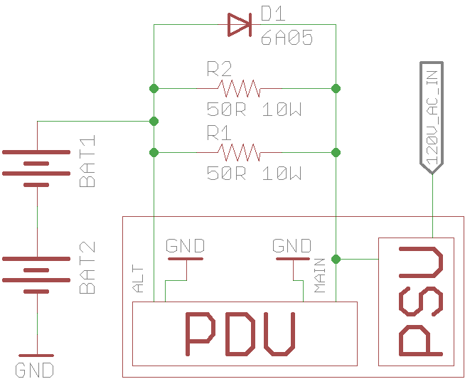
In the diagram, the ALT bus is used to measure the battery voltage directly, so during charging operations with a known resistor value, you can calculate charge current. Additionally during a mains outage you can see the actual battery voltage prior to the 0.7V diode drop.
The diode should be sized (or put in parallel) to support all the current needed to support all devices. The resistor should be sized to limit charge current based on getting the batteries charged in a reasonable timeframe, while not overloading the PSU, while keeping in mind the normal loads from the PoE devices. Somewhere between 5 and 25Ohm is probably reasonable. Be sure these resistors can handle the appropriate power dissipation.
DC Supply or AC With Large Battery Backup
If an external 24V DC supply is available, or a large battery set is desired, the internal PSU will not be of use, simply leave the AC mains unplugged, and supply the PDU DC power. As would follow, in this case an external means of charging the batteries is required.
Design
The PDU was designed with two main power busses, MAIN and ALT. The PDU's onboard logic derives its power from the MAIN bus, so at minimum that is required to be powered. The ALT bus can have a different voltage applied for PoE devices requiring different levels, or the ALT bus can be used as in the AC With Small Battery Backup example, as a voltage sense input. PoE devices are connected to either the MAIN or ALT busses via physical jumpers inside the case. By default all devices are on the MAIN bus.
There are twelve total passthroughs, data comes in from the switch on the bottom port, passes through onboard transformers where power is injected, and the data+power comes out on the top port. Power is individually controlled via MosFETs on each port, and individually metered.
Power switching is handled on the voltage supply side rather than the ground side, using P-Channel MosFETs, to prevent alternative paths to ground (like the metal tower) impacting the ability to control power to the devices.
Overcurrent protection is handled in software by continuously monitoring each port, comparing it against the programmed thresholds, and disabling the supply if it is exceeded.
Software
The PDU software is written in C, and is available on GitHub here. Typically this is compiled with AVR-GCC, and the resulting HEX file is flashed to the PDU via a DFU tool, like the Atmel FLIP utility or the open source dfu-programmer.